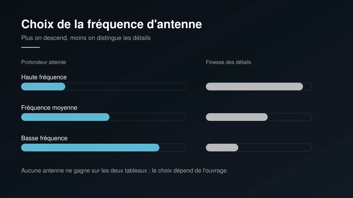
The antenna frequency of a ground penetrating radar decides what a survey can show. A high frequency antenna separates closely spaced targets near the surface but stops short with depth. A low frequency antenna reaches considerably deeper, at the cost of a coarse image where two neighbouring bars blur into one. Neither wins on both counts.
This trade-off is not a specialist footnote. It determines whether a survey answers the question that prompted it. Locating a bar under thin cover and sounding the full thickness of a raft slab do not call for the same equipment. Framing the question before the visit therefore shapes how useful the report will be.
What frequency physically changes inside concrete
A radar emits an electromagnetic pulse that travels through the concrete and reflects at every interface where the properties of the medium change. A steel bar, a duct, a void or the underside of a slab each return an echo. The instrument measures the return time and reconstructs a cross section.
A short wavelength, meaning a high frequency, separates two closely spaced echoes. That is resolution. In exchange, it attenuates quickly as it crosses material. A longer wave keeps its energy further but can no longer distinguish what sits close together. Physics imposes that compromise, and no software setting removes it.
Concrete adds further complexity, because it is not homogeneous. Moisture content, salt content and reinforcement density all influence propagation speed and attenuation. Two slabs of identical thickness will not necessarily behave the same way under the same antenna. The vocabulary behind these measurements is set out in the site glossary.
The common bands and what each one is for
In practice the choice reduces to three families, which are sometimes combined on the same site.
- High frequency for precise location before drilling, over limited thickness
- Mid frequency for ordinary slabs, balancing reach against detail
- Low frequency for thick structures, raft slabs and deep sounding
- Two bands combined when the question concerns both the surface and the depth
Velocity calibration, the step that fixes depth
A radar measures time, not distance. Converting that time into depth requires knowing the propagation velocity in the material being crossed. That velocity shifts with moisture and mix composition. A default value therefore yields a plausible depth, though not necessarily an accurate one.
Calibration means adjusting that velocity against a known reference, such as an object whose depth has been verified, or a measured slab thickness at an accessible point. Without that step, two surveys of the same structure can report noticeably different depths while agreeing closely on plan positions.
The point deserves to be understood by whoever commissions the work, because it explains a common situation: a highly reliable horizontal position paired with a depth given as a range. A clear report separates the two rather than presenting a single depth as a certainty.
Choose from the question, not from the equipment
The sound approach states the question before naming an antenna. Does a short anchor need to miss a bar? High frequency applies. Does the thickness of a structure and a possible void beneath it need establishing? Reach takes priority, and fine detail becomes secondary.
Some requests hold both needs at once. A parking structure survey may require precise location of the upper reinforcement and a sense of the concrete condition deeper down. Two passes with different antennas then beat a single compromise that would fail on both fronts. To frame that choice ahead of a visit, a project description and the pricing details make a practical starting point.
The mistakes that distort interpretation
The first is to demand great depth from a fine antenna, then conclude that nothing lies beneath the slab. The signal simply never reached that far. The second is to read a coarse image as though it carried fine detail, and to mark a position to the centimetre when the band in use cannot support that claim.
A third source of error involves reinforcement density. A tight upper mat reflects much of the energy and leaves little signal for whatever follows. The survey stays valid for that upper layer, yet it says little about what lies below. A serious report states this rather than presenting an absence of echo as an absence of object.
A fourth is subtler still. Surface reflections from nearby metal objects, pipes at the edge of a room or a steel door frame, can appear in the record as though they sat within the slab. Recognising those artefacts takes experience, and it is another reason interpretation matters as much as the equipment. The same caution applies during a structural assessment.
Conclusion
Antenna frequency is not a secondary setting, it is the choice that fixes both the reach and the resolution of a survey. Stating the objective precisely allows the right band to be selected, and sometimes two to be combined. A general overview of the method is available on the ground penetrating radar reference page.
To discuss the band suited to a specific structure, describe the thickness involved and the nature of the search on the contact page. The service itself is outlined on the concrete scanning page.